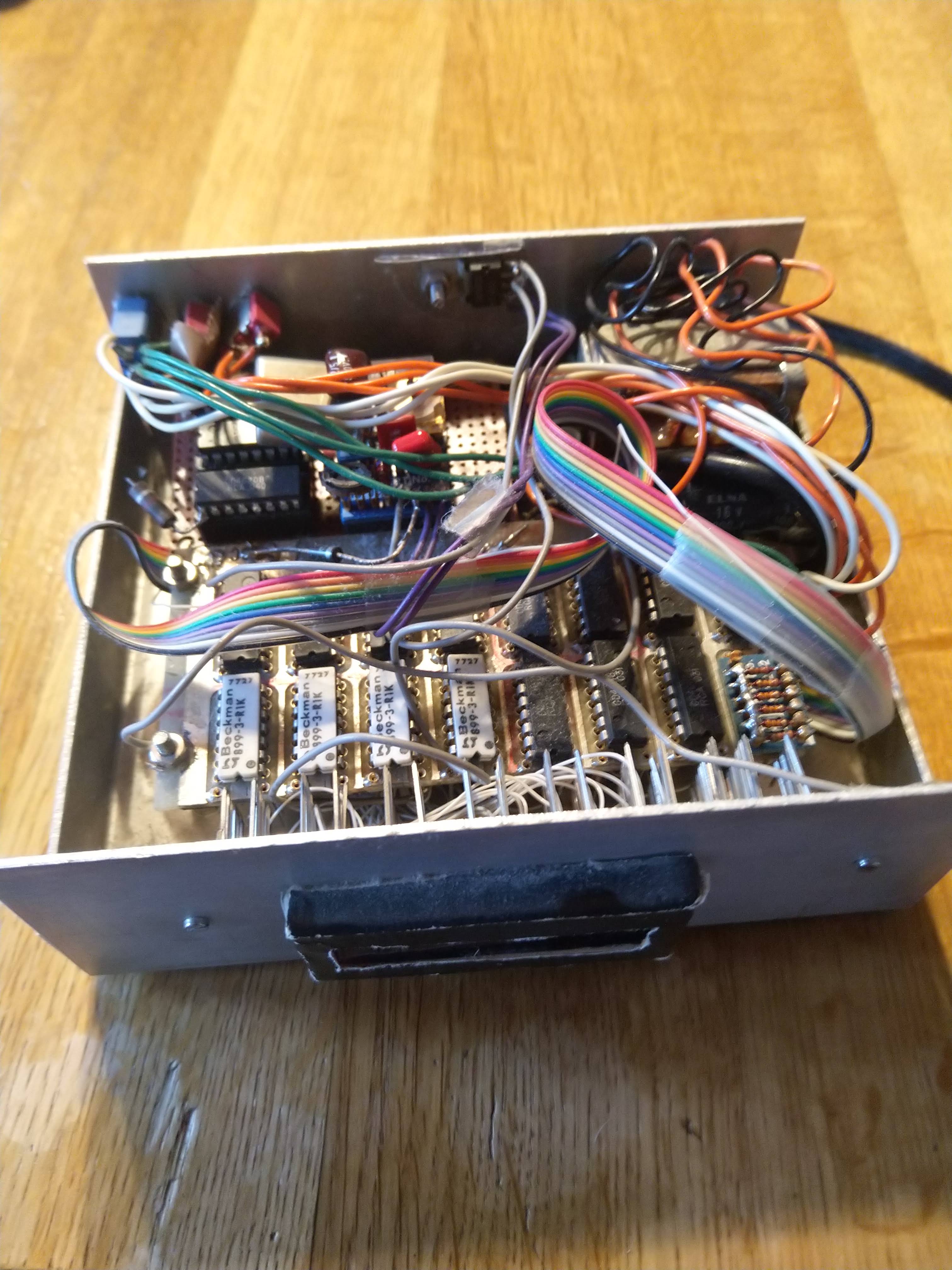
Here is the result of about two weeks’ worth of work.
The year is 1982 in the autumn and all the kids will spend two weeks working somewhere – school is out, it’s called “arbeidsuke”. We are supposed to gain experience from working somewhere. I have discussed working at the local COOP in Tromsø in the audio/video department. This is where they sell the Technics rack that I crave.
Then at the last moment there is a change. Maybe it was the Italian guy called Alessandro who had joined my class, and who had found a place at the Nordlysobservatoriet. He reeked of garlic most of the time, and I think he had curly hair, and he certainly struggled with Norwegian. Suddenly I found myself at the Nordlysobservatoriet in the electronics lab. 3 or 4 guys worked there, and electronics was my great passion, see Til minne om Stein Torp.
As I recall, already on day one I was allowed to play with creating a digital circuit on a Vero board (the one you see above). The integrated circuit was a four-bit counter, and I made it reset itself when it reached a certain value – 10, for instance. With a carry to a second counter it was beginning to look like a clock. Now it would count to 59, and when it hit 60 it would reset itself. This is achieved by using a few AND-gates to detect the number 60 and use the output to reset the counter. So, the value 60 is present at the outputs for a very short time. Not the most elegant solution, but it works.
What I remember, though, is the excitement of going to work every morning with the anticipation of working on my circuit. Piece by piece I added more counters to make a 24-hour clock. I then added a LED-driver integrated circuit which decodes BCD to a standard LED display, and wired it all together. The white ICs on the left contain 7 resistors used to drive the LED. Now I needed a clock pulse, and this comes from a crystal and a counter or two – the result is a 1 HZ signal. It took trial and error to stabilize the crystal, and if I remember correctly a small capacitor in parallel did the trick, probably shorting a higher harmonic to force the crystal to oscillate at its main frequency, the one stamped on the outside. I used a digital analyzer to inspect all the waveforms. Probably Hewlett Packard.
The final steps where a voltage regulator, a transformer, a bridge rectifier, a smoothing capacitor… the regulator IC was a quite expensive one.
The people in the mechanics lab helped me make a metal chassis, and the whole setup was finished before my two weeks were up. I added two push-to-make switches for setting the time.
One day I could not work on the circuit – we drove to the telescope station deep inside Troms, at Skibotn (see this link). That was quite interesting, but I don’ remember much!
The clock still runs all this years later, but I don’t use it anymore.

Wow! I’m impressed. Must have been fun.